
TLDR
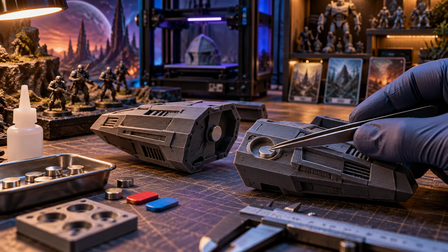
Treat a magnet pocket as an assembly system, not a nominal-size hole. Measure the actual magnets, print a fit coupon, and choose either a removable slip fit, adhesive-retained clearance fit, or carefully tested interference fit. Mark one master magnet and use an insertion jig to control polarity. Let pins, ledges, sockets, or keys carry side loads while the magnets provide alignment and closing force. Finally, inspect every assembly for loose magnets—especially if children could reach it.
If your project notes currently read “magnets 3d printed models polarity pockets,” the practical answer is to separate the problem into four decisions: fit, retention, polarity, and load path. A pocket that succeeds at only three can still ruin a model. Perfect attraction does not help when the magnet protrudes, spins in its recess, splits a resin wall, or faces the wrong pole.
There is no dependable universal pocket offset or wall thickness. Printed dimensions change with the machine, material, orientation, calibration, first layer, and finishing process. The reliable workflow is to parameterize the pocket, print a small test coupon, and use the winning dimensions in the final model.
Start with the actual magnet, not its product name
A magnet sold as a particular diameter and thickness gives you a specification to order, not a guaranteed measurement for your CAD file. Measure samples from the batch you will install. For a disc, record diameter and thickness. For a block, measure all three axes. A countersunk magnet also requires the hole diameter, countersink diameter, countersink depth or angle, and the direction of the countersink.
Measure several pieces rather than choosing the most convenient one. Your pocket must accommodate normal batch variation, coating variation, and any burr or adhesive residue introduced during assembly. Also inspect the edges. A chipped coating or sharp corner can scrape a tight pocket and create an unpredictable fit.
Build the CAD pocket from named parameters such as magnet diameter, pocket allowance, magnet thickness, depth allowance, chamfer, and back-wall thickness. For a rectangular magnet, keep the width and length allowances separate. Editing one parameter is much safer than remodeling every recess after a test print fails.
Tune 3D printed magnet pockets with a test coupon
A CAD pocket that exactly matches the magnet is not necessarily a matching printed pocket. FFF holes can print inaccurately depending on the material and settings, and may need post-processing when accuracy matters. First-layer spreading, commonly called elephant foot, can also distort functional geometry near the build plate. Prusa similarly recommends allowing for dimensional effects such as shrinkage and warping rather than assuming mating features will emerge at their nominal dimensions.
Print a small coupon containing several labeled pockets generated from the same parameterized design. Include the intended print orientation, pocket entry shape, wall construction, layer height, and material. A horizontal cylindrical recess and a vertical open pocket are not equivalent tests. If the final part will be sanded, washed, cured, painted, or coated before assembly, apply the same process to the coupon.
| Coupon fit | Useful for | What to check |
|---|---|---|
| Loose slip fit | Removable prototypes or pockets that will receive a retaining cap | Magnet enters freely and can be removed without damaging the pocket |
| Controlled clearance | Adhesive-retained installation | Space remains for adhesive without allowing severe tilt or misalignment |
| Snug fit | Light-duty assembly or positioning before another feature traps the magnet | Magnet seats with modest force and does not scrape or stress the wall |
| Interference fit | Only a validated material, geometry, and load case | Insertion force, cracking, layer separation, long-term loosening, and serviceability |
Formlabs treats fit as something to tune through printing and testing, distinguishing press fits from looser fit classes rather than prescribing one offset for every printer and material. That approach applies equally well here: clearance is an output of your tested process, not a magic number copied from another maker’s machine.
Evaluate diameter or width separately from depth. A magnet can slide into a recess while still standing proud because the floor is too high, debris is trapped underneath, or the pocket has a rounded internal transition. It can also sit flush but rattle sideways. Label every coupon pocket so the successful parameter does not become bench-top archaeology ten minutes later.
Press fit or glue: choose retention for the part
An adhesive-retained clearance fit is usually the forgiving choice for painted models, interchangeable accessories, and parts with thin or brittle walls. It avoids high insertion force and gives you time to verify polarity. The pocket should constrain gross movement while leaving enough room for the chosen adhesive system. Confirm that the adhesive is compatible with both the printed material and the magnet’s coating, then test it on scrap. Cure it according to its manufacturer’s directions before applying load.
A press fit eliminates a separate bonding step, but transfers installation force directly into the print. That can split a thin FDM wall along layer lines or crack a rigid resin part. Use it only after testing the final material, orientation, geometry, and magnet batch. Press the magnet squarely with a flat tool rather than driving one edge down first.
The strongest practical retention often combines moderate fit with mechanical containment. Options include a printed cap, screwed cover, snap-in plug, retaining lip, dovetail insert, or a pocket trapped when two model halves are joined. Mechanical containment is especially valuable in handled props, terrain, articulated models, and objects that may be dropped. Adhesive then becomes backup retention instead of the only thing preventing a small magnet from escaping.
Design the pocket without creating a crack starter
Add a small lead-in chamfer at the pocket entrance. It guides the magnet, reduces edge scraping, and makes square insertion easier. Provide a positive depth stop so the magnet cannot disappear below the intended mating plane. If future removal might be necessary, include a rear access hole or another deliberate extraction route before printing.
Do not place a tight pocket beside a cosmetic outer surface with only a fragile shell between them. Increase local material, add a boss around the recess, or move the magnet inward. Rounded transitions can reduce abrupt stress concentrations. In FDM parts, consider whether insertion or service loads will try to separate layers. Reorienting the print or redesigning the boss may be more effective than simply adding global wall thickness.
Open pockets facing the build plate deserve particular suspicion because first-layer distortion can narrow their entrances. Move the opening away from the first layer, compensate through a tested design feature, or plan a controlled finishing step. Do not force a magnet through a visibly flared or undersized entrance and hope the plastic negotiates a treaty.
Control polarity before any magnet is permanently seated
Choose one magnet as the marked master. Identify one face with paint or a removable label and define what that face means—for example, “outward face on every base component.” Keep this convention consistent across the project. A polarity chart or exploded assembly drawing becomes essential when a model has multiple limbs, weapon options, doors, or modular terrain panels.
A polarity jig is a simple holder that accepts the master magnet or an already verified component and presents the installation magnet in only the correct orientation. The jig may be a tube, handle, keyed block, or insertion plunger. Its job is not to measure magnetic north and south; it transfers a known mating orientation repeatedly while keeping fingers away from the pocket.
- Mark and isolate the master magnet.
- Use the master to orient the first magnet in each component family.
- Mark the exposed installation face before applying adhesive.
- Dry-fit the complete pair and confirm attraction.
- Load the magnet into a keyed jig without flipping it.
- Seat it to the depth stop and keep the jig steady while initial retention is established.
- Verify the finished component against the master before moving to the next pocket.
When installing multiple magnets close together, work in a planned order. An already seated magnet can pull the next one off the tool, flip it, or drag it through uncured adhesive. Temporary nonmagnetic spacers and a jig with positive depth control make the process less exciting—and magnet installation is one hobby task that benefits from being boring.
Design for pull, shear, and air gaps
A listed pull force does not describe every printed joint. Direct axial pull separates two aligned magnet faces along their shared axis. Shear loading tries to slide one face across the other. A supplier demonstration from K&J Magnetics shows that shear behavior can differ substantially from modeled axial pull in the tested door arrangements; it should not be treated as a universal conversion percentage.
This matters for a model held vertically. Magnets may snap the pieces together convincingly, yet the attached part can creep downward because its weight acts sideways across the mating faces. Paint, plastic skins, imperfect alignment, and recessed magnets also create an air gap. Even a small gap can make the completed joint feel weaker than two bare magnets tested directly together.
Let geometry carry predictable side loads. Add a ledge beneath a removable panel, a pin-and-socket pair for an arm, a keyed tongue for a weapon, or a shallow locating rim around a base. The hard features resist sliding and rotation; the magnets pull the pieces together and keep them seated. This produces a more reliable assembly than trying to solve every load by buying a stronger magnet.
Special caution for resin prints
Resin can reproduce a precise-looking recess, but visual precision does not make an aggressive press fit safe. Rigid resin parts may crack with little warning when a magnet is forced into an undersized hole. Print fit coupons in the same resin, orientation, support strategy, wash process, and cure conditions as the final part. Remove debris and confirm the pocket is fully cured before assembly.
Favor controlled clearance and secondary retention when the wall is thin or the part is difficult to replace. If a press fit is genuinely necessary, test sacrificial copies and inspect them under strong light after insertion. Whitening, hairline cracks, or a changed sound during pressing are reasons to stop rather than apply more force.
Troubleshooting common failures
- Pocket too tight: confirm the magnet measurement, inspect for elephant foot or trapped support material, and return to the coupon rather than forcing the magnet.
- Pocket too loose: revise the parameter, add a tested adhesive system, or use a plug or cap. Do not rely on a thick blob of adhesive to center a visibly wandering magnet.
- Magnet stands proud: check pocket depth, floor debris, internal corner geometry, and excess adhesive beneath the magnet.
- Part cracks during insertion: stop using that interference fit. Increase clearance or local reinforcement, reconsider print orientation, and test again.
- Joint attracts but slides: add keyed geometry or a supporting ledge and reduce the gap between mating faces.
- Joint feels unexpectedly weak: verify polarity, alignment, seating depth, surface coatings, and whether the load is primarily shear rather than direct pull.
- Magnet was installed backward: use a designed extraction opening if available. Otherwise, replacing the affected component may cause less damage than drilling or prying near a brittle wall.
Small-magnet safety is part of the design
Loose high-powered magnets can cause severe internal injuries if multiple magnets—or a magnet and a magnetic metal object—are swallowed and attract through intestinal tissue. The U.S. Consumer Product Safety Commission’s magnet safety guidance says to seek immediate medical attention if ingestion is suspected. It also warns that multiple swallowed magnets can appear as a single object on an X-ray. Do not wait for symptoms or attempt to solve suspected ingestion at the hobby bench.
Keep loose magnets organized and out of reach of children. Count them before and after assembly, clean dropped pieces from the work area, and inspect finished models periodically. If a magnet is accessible, a mechanical cap or trapped pocket is preferable to adhesive-only retention. A display model can become a handled object later, so design for foreseeable drops, wear, and curious fingers.
Final assembly checklist
- Measure several magnets from the actual batch.
- Parameterize width or diameter, depth, allowance, and surrounding material.
- Print and label a representative fit coupon.
- Select the retention method for the material and real load.
- Add a chamfer, depth stop, and extraction route where practical.
- Mark a master magnet and document the polarity plan.
- Dry-fit every mating pair before permanent installation.
- Use keys, pins, sockets, or ledges to resist shear and rotation.
- Allow adhesive to cure as directed before load testing.
- Inspect the completed model for cracks, movement, and loose magnets.
Build the joint as a system
Reliable magnetic models come from controlling the whole assembly, not chasing one perfect pocket dimension. Measure the hardware, tune the print, select retention deliberately, lock down polarity, and give side loads a mechanical path. Start with a coupon and one complete prototype joint before committing to a full batch. That small test can save a finished paint job, a fragile model, and an entire squad of backward-facing magnets.