
TLDR
Design 3d printed prop LED wiring channels around assembly and repair, not merely around hiding wires. Divide the prop into power, control, lighting, and removable shell modules. Give wires protected routes, leave clearance around joints and connectors, make the battery accessible, and test the complete electronics package before sealing anything. For most builds, an open groove or covered raceway is easier to print and service than a fully enclosed tunnel.
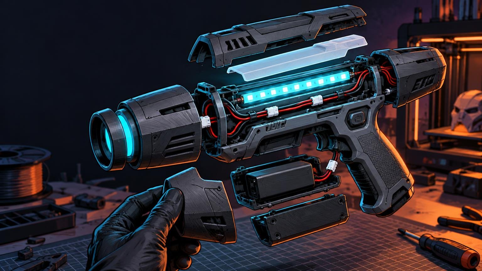
A glowing prop can look perfect in CAD and still become an assembly nightmare when a connector will not pass through a hole or a shell seam crushes the LED leads. The solution is to plan the internal architecture before polishing the exterior. Good 3d printed prop LED wiring channels help the prop close cleanly, but the better goal is a system that can also be charged, opened, diagnosed, and repaired.
Treat the prop as a group of modules
Start by dividing the electronics into functional modules. A typical illuminated prop may have a battery and charging section, a control board, a switch or button, one or more lighting assemblies, and connectors between removable body sections. Sketch these components as physical objects rather than abstract circuit symbols.
Place the largest and least flexible parts first. A battery, circuit board, switch body, USB plug, or rigid LED strip dictates more of the internal layout than a flexible wire does. Import simplified models of those parts into CAD when possible. Include the connector housings, solder joints, mounting hardware, and the space needed by fingers or tools during assembly.
Modularity becomes especially important when a long prop must separate for transport. The same removable batteries and protected joints that make a build easier to repair can also make it easier to pack; the broader cosplay prop transport design guide covers that travel-focused side of the decision.
Choose the printing process after considering the size, detail, strength, and finishing needs of each module. A large structural shell and a small translucent detail do not necessarily need the same process or material. The FDM versus resin guide for props and miniatures can help divide those jobs sensibly.
Choose the right type of wire channel
There is no universal channel width or depth. Measure the actual insulated wires at their widest point, then account for paired wires, splices, bends, print variation, and the way the route will be assembled. A short test coupon containing several candidate channel sizes is faster and cheaper than discovering the problem inside a finished hilt.
| Channel style | Best use | Main tradeoff |
|---|---|---|
| Open groove | Accessible shell interiors and early prototypes | Easy to print, inspect, and revise, but it needs clips, adhesive, or a cover to retain the wire. |
| Covered raceway | Serviceable wiring that needs protection during assembly | A removable or snapped-on cover protects the route without permanently trapping the wire. |
| Enclosed tunnel | Short, simple passages through otherwise inaccessible geometry | Clean exterior, but difficult to clear, inspect, rewire, or print if support material becomes trapped. |
| Pass-through hole | Moving wires between compartments or shell sections | Compact and useful, but the edge and bend must not cut, pinch, or sharply turn the wire. |
| Connector pocket | A controlled location for a modular disconnect | Keeps the connection from rattling, but must leave room to grip and release the connector. |
Open grooves are the safest default during development because every wire remains visible. Add printed tabs, bridge clips, a removable cover, or another retention method after confirming the route. Use enclosed tunnels selectively, especially where the path curves or a connector would need to pass through it.
Avoid sharp internal corners. Route wires with smooth changes of direction, and give soldered ends room to leave a board or LED strip without immediately bending against the joint. Retention should act on insulated wire or an appropriate connector body rather than loading a fragile solder joint.
Design battery access before cosmetic seams
A battery should not require cracking glue joints or removing half the prop for routine access. Depending on the shape, use a removable endcap, secured panel, sliding tray, or complete electronics sled. Place the opening where the battery can be inspected and removed without pulling on its leads.
Adafruit’s DIY Darksaber hilt assembly demonstrates a useful service pattern: its USB port remains accessible through the bottom of the hilt, while a press-fit pommel can be removed to reach the internal assembly. The same build intentionally routes speaker, LED-strip, and button wires through slits in the battery holder rather than leaving them loose during closure.
For a magnetic access panel, model positive alignment features so the magnets hold the panel closed rather than carrying every shear and twisting load. Plan polarity and pocket fit before bonding anything; the guide to magnets in 3D printed models explains the pocket and assembly considerations in more detail.
Keep charging access practical. A visible opening is not enough if the cable plug hits the shell before fully engaging or cannot be removed without tugging its wire. If the battery manufacturer requires removal for charging, design the prop around that procedure rather than burying the pack behind a convenient-looking port.
Make switches and ports usable, not merely visible
Model the entire switch body, not only the button seen from outside. Check actuator travel, threads or mounting tabs, nut clearance, solder terminals, wire exit direction, and tool access. A recessed control also needs enough surrounding space for a gloved finger if the prop will be used with a costume.
Ports need similar attention. Test the real USB or charging cable because plug housings vary. Align the port so insertion force is supported by the internal mount instead of flexing a circuit board. Adafruit’s light-wand assembly uses a dedicated switch opening and rails for PCB holders, illustrating how the enclosure can locate controls and electronics instead of asking loose components to find their own positions.
Prevent pinched wires at every joint
Shell seams, screw bosses, alignment pins, and sliding joints are common pinch points. In CAD, reserve a wire-free boundary around each one. At a removable section, include a controlled service loop: enough slack to open the part and disconnect it, but not so much that the wire folds into the seam when the part closes.
Inspect the assembly sequence one step at a time. Ask where each wire sits as the shell halves approach, where excess length moves, and whether a screw can enter the wiring space. A channel that works in the final closed model may still fail during the motion required to reach that position.
- Keep wire paths away from screw tips, threaded inserts, and moving latches.
- Add rounded pass-throughs where wires cross printed walls.
- Provide strain relief before wires reach solder joints or delicate board connectors.
- Retain loose runs so gravity cannot drop them into a seam during closure.
- Leave connector pockets accessible without forcing the user to pull on the wires.
Place connectors for modular assembly
Use disconnects where the prop must separate for printing, transport, battery service, or repair. Select them according to the circuit’s electrical requirements, available space, polarity needs, and expected connection cycles. Keyed or otherwise unmistakable connections reduce the chance of reversing a module during hurried convention-floor repairs.
A connector pocket should restrain the housing while still exposing the release area. Orient the connector so it can be engaged and unplugged along a clear path. Do not bury it at the bottom of a narrow cavity that can only be reached by pulling its leads with tweezers—the dark side may offer many shortcuts, but that one leads directly to a broken solder joint.
Before printing the full shell, make a small connector test piece. Check insertion, release, wire bend direction, and whether both halves can be handled once surrounding prop sections are present. Add labels or distinctive connector arrangements when several similar lighting modules meet in one cavity.
Build diffusion as a separate optical system
A diffuser is not simply a translucent wall added at the end. LED spacing, distance from the diffuser, surface texture, wall thickness, material color, and the shape of the light chamber all affect visible hot spots. Prototype a short representative section using the actual LEDs and intended brightness before printing a full blade, crystal chamber, or illuminated panel.
A useful light module separates the structural shell, reflective or light-mixing cavity, LED support, and removable diffuser. This lets you adjust the optical parts without reprinting the entire prop. Adafruit’s IRIS LED and Prop Guards project uses a translucent printed cap to protect and diffuse NeoPixel rings, while also accounting for wire passage and USB alignment in the enclosure.
Test the prototype in the lighting conditions where the prop will be seen. A diffuser that looks smooth in a dim workshop may reveal individual LEDs in a dark room or wash out under convention-hall lighting. Adjust spacing and geometry from the physical result rather than relying on one supposedly universal diffuser dimension.
Respect heat and battery boundaries
Heat planning must consider the real LED load, control electronics, wiring, duty cycle, ventilation, print material, and assembled runtime. Consult the data sheet for the exact filament used rather than treating a material name as a guarantee. For example, Ultimaker states that use above 76°C is unsuitable for its specific PETG formulation; that figure is not a universal limit for every product sold as PETG.
Run the completed electronics while they are still accessible and observe the battery, connectors, boards, LEDs, and nearby printed surfaces. Stop if components become unexpectedly hot, deform, smell abnormal, flicker, or behave inconsistently. Follow the battery and charger manufacturers’ instructions, and do not use a damaged or swollen pack.
Most importantly, do not describe an ordinary printed prop shell as a battery-containment enclosure. UL Solutions explains that lithium-ion thermal runaway can involve uncontrolled self-heating, fire, very high temperatures, and hazardous gases; its containment work concerns purpose-built enclosures subjected to dedicated evaluation. A hobby shell should provide access and physical organization, not be treated as certified protection against battery failure.
Print and test in stages
Do not commit the whole prop to a long print as the first fit check. Print small slices around the highest-risk features: the switch opening, charging port, connector pocket, diffuser interface, battery tray, and curved wire passage. Test with the real components, fasteners, wires, and cables.
Once those interfaces work, perform a dry assembly without adhesive. Install the electronics in the intended order, close every seam, operate every control, and reopen the prop. If reopening requires pulling on wires or prying against a board, revise the design before finishing and paint make changes expensive.
Pre-seal checklist
- Confirm polarity and continuity before connecting the battery.
- Test every LED, switch, control mode, speaker, and other powered feature.
- Verify that charging and programming ports accept the actual cables.
- Check that connectors fully engage and can be released without pulling their wires.
- Open each battery door, endcap, access panel, and electronics sled using the intended tools.
- Close all shell seams while watching for displaced or pinched wires.
- Confirm that screw tips, inserts, and latches cannot enter a wire route.
- Check diffuser alignment, retention, brightness, and visible hot spots.
- Run the assembled electronics for a realistic operating period while they remain accessible, watching for abnormal heat or behavior.
- Photograph or label the internal connector layout before final closure.
Design for the repair you hope never to make
The best LED layout is not the one that hides every wire most aggressively. It is the one that guides each wire safely, lets modules separate cleanly, and provides access to the parts most likely to need charging, adjustment, or replacement.
Begin with a block layout of the battery, controller, lights, switches, ports, and connectors. Then choose channel types, print interface coupons, and perform a complete powered dry fit. A little extra CAD work before printing turns a glowing prop from a sealed electronic puzzle box into a build you can maintain for years.
References
- Hilt Assembly | DIY Darksaber Build – 3D Print with PropMaker FeatherWing and BLE | Adafruit Learning System
- Assembly | Light Up Prop with Prop-Maker | Adafruit Learning System
- Overview | IRIS LED and Prop Guards | Adafruit Learning System
- Ultimaker
Ultimaker PETG
Technical data sheet - Testing and Certification for Battery Containment Enclosures (BCE) | UL Solutions